Autonomous Mars Habitat Robot
Custom motor electronics, mixed-signal sensing, PCB design & embedded hardware integration
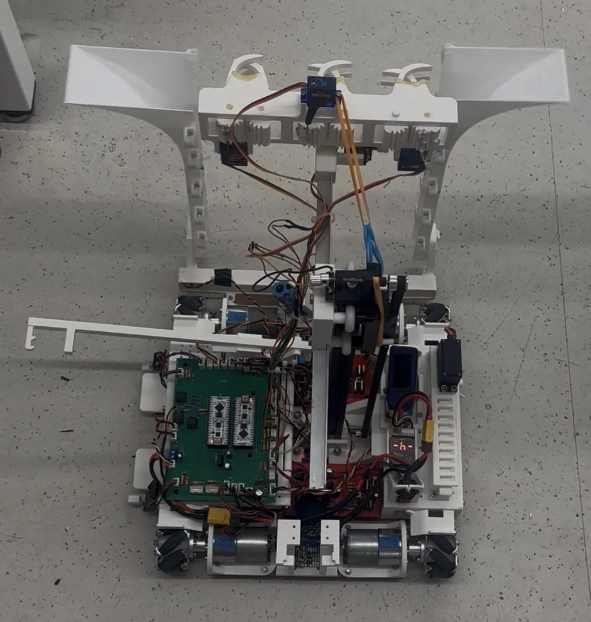
My team and I built an autonomous rover for a two-minute Mars habitat challenge. I focused on the electrical system: custom motor-control boards, PCB integration, power distribution, modulated IR sensing, actuator electronics, and the hands-on work of bringing the hardware together and debugging it on the robot.
Team project · My focus: electrical design, PCB integration, sensing, actuator electronics, bring-up, testing and debugging
- Brushed DC motor channels
- 5×
- Core custom PCBs
- 3×
- ESP32 controllers
- 2×
- IR beacon frequencies
- 1 / 10 kHz
- Stepper, servo & DC actuation
- 3 types
- Embedded interfaces
- I2C + UART
Build a Mars habitat in two minutes
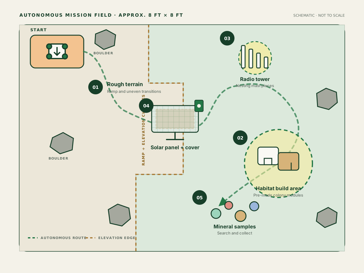
The course challenge was to build a fully autonomous, battery-powered rover for a two-minute mission on an approximately 8 ft × 8 ft field. Starting from one corner, the robot had to cross ramps and uneven terrain before completing a mix of navigation, object-handling, and construction tasks.
The mission combined five distinct objectives: reach the habitat site, assemble a habitat, build a radio mast, uncover a solar panel, and collect mineral samples. That variety drove our mecanum chassis and multi-actuator design. My job was to make the electrical pieces behave as one system while the rover was moving, vibrating, and drawing rapidly changing current.
-
Traverse rough terrain
Leave the start zone and cross ramps and uneven transitions to reach the habitat site.
-
Assemble the habitat
Position and assemble pre-made modules inside the designated colony building area.
-
Build the radio tower
Handle and nest the mast segments together inside the tower build area.
-
Activate the solar array
Find the solar panel using its modulated IR beacon, then remove the protective cover.
-
Collect mineral samples
Search the field for mineral targets and retrieve them for future manufacturing.
A full-system test on the physical course
This two-minute recording puts the electrical work in context. Away from the bench, locomotion, sensing, communication, power delivery, and mechanism timing all had to hold together as one autonomous system.
- ≈ 2 minute run
- Physical course
- Integrated hardware
Electrical system architecture
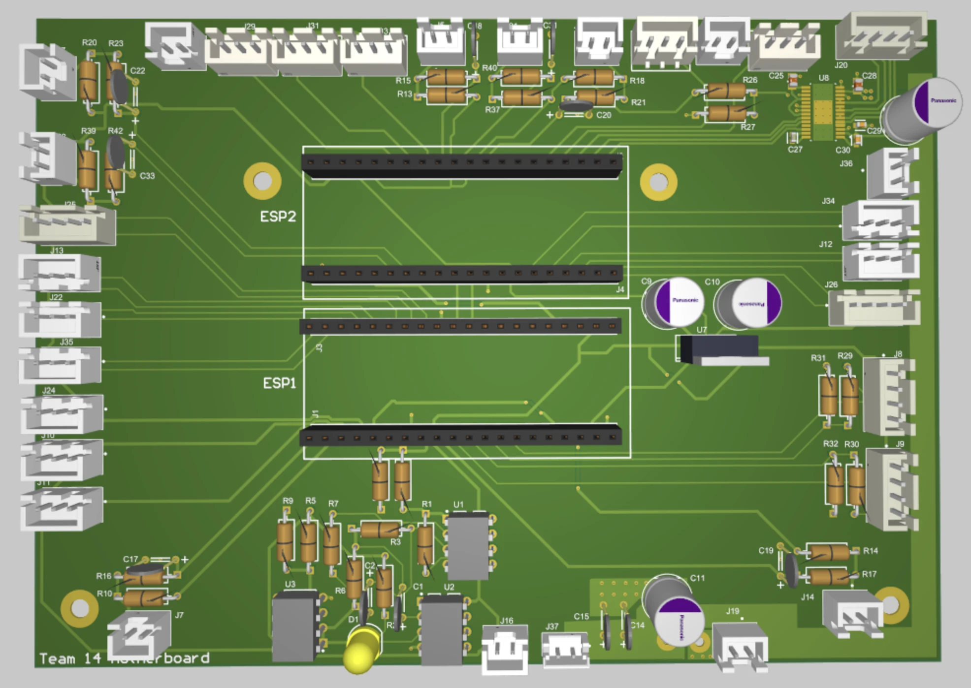
I distributed the electronics across custom PCBs instead of wiring the rover entirely from loose development modules. The hardest part was not connecting one sensor or motor; it was moving power, commands, and measurements reliably through a compact, electrically noisy machine.
Battery / main power
Protection / fuse
High-current distribution
Regulated logic rails
Custom brushed DC motor channels
DRV8425 stepper stage
Servo & DC actuators
ESP32 controller #1
ESP32 controller #2
IR analog front end
Reflectance sensors
Distance sensors
MPU-6050 IMU
Limit switches
This system map shows how I organized the electrical design around three domains: high-current actuation, embedded control, and sensing.
- PWM
- Brushed DC motor control
- STEP / DIR
- Vertical stepper mechanism
- Servo PWM
- Mechanism actuation
- ADC
- IR receiver acquisition
- I2C
- MPU-6050 heading data
- UART
- Controller-to-controller communication
- Digital I/O
- Line sensors & limit switches
Custom motor drive electronics
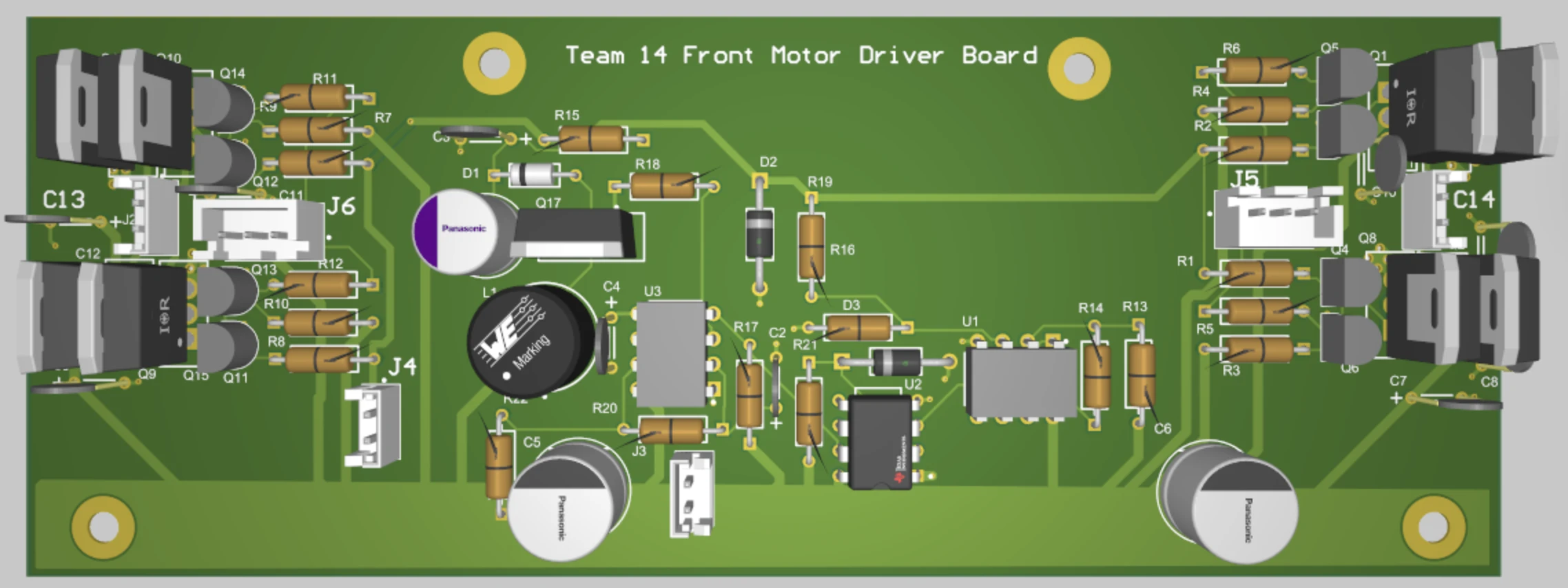
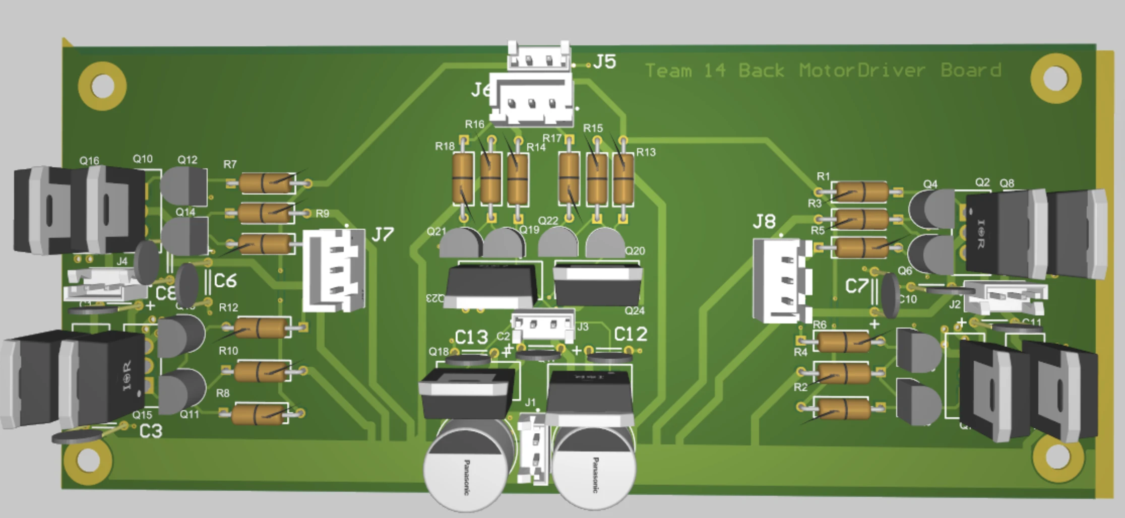
The rover used five brushed DC motor channels, including the mecanum drivetrain. Because the course rules did not allow us to rely on a ready-made H-bridge module, I worked through the MOSFET power stage, PCB layout, board bring-up, and component-level fault finding.
I had to translate low-voltage PWM into dependable high-side and low-side switching while thinking about motor current, switching transients, and shoot-through. That pushed me to pay much closer attention to gate drive, bulk and local decoupling, motor-noise suppression, connector ratings, and the geometry of high-current copper paths.
Once the design became a real board, placement and wiring mattered just as much as the schematic. MOSFET spacing, connector position, return-current paths, and the board's location beside the drivetrain all affected how practical the design was to assemble and debug.
- High-side / low-side gate drive
- PWM switching behaviour
- Current & return paths
- Bulk and local decoupling
- Motor-terminal suppression
- Trace width & connector current
Modulated IR beacon receiver
One task required the rover to find a solar panel using an IR beacon modulated at either 1 kHz or 10 kHz. I could not treat that as a simple light-versus-dark measurement because ambient light and electrical noise would make a raw threshold unreliable.
I used a phototransistor with analog filtering and amplification to condition the signal before it reached an ESP32 ADC. In firmware, a Goertzel-based calculation looked specifically at the two expected frequencies, giving the robot a much more useful signal for alignment than total light intensity alone.
This part of the project taught me that the analog circuit, sampling window, detection latency, sensor position, and mechanical alignment all had to be tuned together. A clean signal on the bench only became useful when it produced repeatable behaviour on the assembled rover.
- ADC sampling rate & window length
- Ambient-light rejection
- 1 kHz / 10 kHz discrimination
- Detection latency
- Physical sensor placement
- Repeatable panel alignment
Power distribution & mixed-signal integration
I was placing sensitive analog and digital electronics beside brushed motors, a stepper driver, servos, DC actuators, and switching regulators. That made power distribution, signal integrity, and physical packaging part of the same problem.
- 5× brushed DC motors
- Stepper driver
- Servos
- DC actuators
- Switching regulators
- IR analog front end
- ESP32 ADC
- I2C IMU
- Line sensors
- Limit switches
- 01Local decoupling at active devices
- 02Bulk capacitance near dynamic loads
- 03Short, deliberate high-current return paths
- 04Motor-terminal noise suppression
- 05Power and signal routing separation
- 06Serviceable connectors and strain relief
During integration, I repeatedly recrimped and reorganized wiring so the robot was easier to service and less likely to fail when handled. It reinforced a simple lesson: on a moving robot, a connector or wire that cannot survive normal use is still an electrical design problem.
Stepper / linear actuator electronics
I used a DRV8425-based stepper stage for the vertical mechanism. When the first commands produced no motion, I stopped treating it as a software problem and started measuring the driver directly.
- Supply rails
- FAULT
- ENABLE
- STEP
- DIR
- Charge pump / boosted rail
By probing the control pins and supply nodes, I found issues around the FAULT / ENABLE configuration and charge-pump circuitry. I reworked the board, corrected the hardware, and then confirmed that the driver could move the stepper.
After bring-up, I integrated the stage with a lower limit switch for homing, STEP / DIR control, and adjustable travel limits. The biggest lesson was to verify every layer—from the command waveform to the driver's internal supply—before blaming the mechanism.
Sensor & embedded integration
Two ESP32 controllers tied the drivetrain and mechanisms to the rover's navigation and safety sensors. I kept the interfaces conventional and easy to inspect: ADC for the IR receiver, I2C for the IMU, UART between controllers, and digital inputs for reflectance sensors and switches.
- Reflectance / line sensing
- MPU-6050 over I2C
- Ultrasonic / distance sensing
- Limit switches
- ESP32 ADC
- Controller UART
Late in integration, the MPU-6050 began failing in a way that looked electrical. I moved the sensor, inspected SDA and SCL, noticed that probing could disturb the bus, switched to a 10× probe, added local decoupling, and tracked both read failures and bus health. The final cause turned out to be software rather than the physical I2C bus.
The electrical investigation was still valuable because it let me rule out the suspected hardware causes with evidence instead of assuming that the last change had fixed the problem.
Hardware bring-up & failure analysis
I learned the most when a board did not work immediately. In each case, I used measurements to narrow a system-level symptom into a specific, repairable cause.
H-bridge power short
- Symptom
- A motor-driver board developed a severe VCC-to-ground short and repeatedly opened the system fuse.
- Investigation
- I disconnected the load, checked resistance across the power rails, and isolated sections of the bridge until I found the damaged devices.
- Root cause
- I confirmed that MOSFETs in one bridge had shorted. Accidental contact at an exposed high-current node was a plausible trigger, but I could not prove it conclusively.
- Fix / outcome
- I removed and tested the failed parts, repaired the bridge, and inspected the nearby mechanical and electrical contact points before powering it again.
Separate what I measured from what I only suspect.
Stepper fault & charge pump
- Symptom
- The vertical stepper mechanism did not move during initial board bring-up.
- Investigation
- I probed the supply rails, FAULT, ENABLE, STEP, DIR, and charge-pump behaviour directly at the driver.
- Root cause
- The hardware configuration around FAULT / ENABLE and the charge-pump circuitry was preventing correct operation.
- Fix / outcome
- I reworked the PCB, corrected the hardware issues, and verified motion before adding homing and travel limits.
A valid command waveform does not prove that the power stage is ready to switch.
Intermittent IMU behaviour
- Symptom
- Late-stage heading failures initially looked like an I2C signal-integrity problem.
- Investigation
- I relocated the IMU, inspected SDA and SCL on the oscilloscope, changed to a 10× probe after noticing probe interaction, added local decoupling, and tracked read failures.
- Root cause
- The final cause was software rather than the physical bus.
- Fix / outcome
- The measurements let me rule out the suspected electrical causes and redirect the investigation toward firmware.
Good instrumentation narrows the fault domain, even when my first hypothesis is wrong.
Designing for testability
I could only bring the rover up efficiently when its internal state was visible. I tested one actuator or sensor at a time, checked rails and waveforms with a DMM and oscilloscope, and used live telemetry while the assembled robot was moving.
- Oscilloscope
- DMM
- Bench tests
- Live telemetry
- Adjustable thresholds
- Isolated actuator tests
- Sensor diagnostics
I treated telemetry as a hardware tool. Seeing ADC readings, sensor states, IMU health, motor parameters, and manual actuator controls made it much faster to turn a vague system symptom into a specific probe point and a repeatable test.
Final integration
The finished electrical system connected mecanum drive, IR alignment, line sensing, IMU heading, a vertical stepper mechanism, servos, limit switches, and distance sensors in one autonomous rover.
- 01Improved sensor mounting and positioning
- 02Recrimped and reorganized wiring
- 03Improved mechanical actuation of limit switches
- 04Added or revised local decoupling
- 05Made alignment thresholds adjustable
- 06Reduced nonessential communication during autonomous operation
Near the end, my work was less about adding features and more about removing ambiguity: firmer connections, repeatable sensor geometry, cleaner power behaviour, and measurements that made failures easier to diagnose.
What I took from it
The project resulted in an integrated autonomous rover and a set of custom electronics that I could bring up, repair, and refine under real system constraints. More importantly, it changed how I approach electrical design: I now think about test points, current return paths, connectors, sensor placement, and failure modes from the start.
- Integrated rover
- I brought the motor, sensing, control, and actuator electronics together on the physical platform.
- Custom hardware
- I gained practical experience designing and integrating custom motor-driver and controller PCBs.
- Measured debugging
- I used scope, DMM, and telemetry data to isolate faults instead of relying on trial and error.
Key engineering takeaways
I now design around failure modes
High-current electromechanical hardware exposed problems that isolated logic-circuit testing could not.
I measure before I guess
PWM, I2C, fault-signal, and rail measurements narrowed faults faster than blind code or component changes.
Hardware and firmware have to be debugged together
Several failures only became understandable after I paired electrical measurements with firmware instrumentation.
Mixed-signal integration needs deliberate boundaries
Motor PWM, switching regulators, and actuators had to coexist with a comparatively sensitive IR and ADC signal chain.
Mechanical reliability is electrical reliability
Connector movement, sensor position, and limit-switch actuation can all look like circuit or firmware faults.